
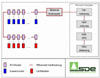
SDE offers modular software components around the
different processing steps of a modern sawmill.
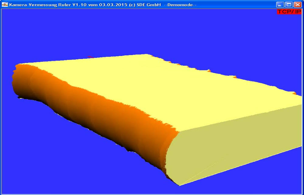
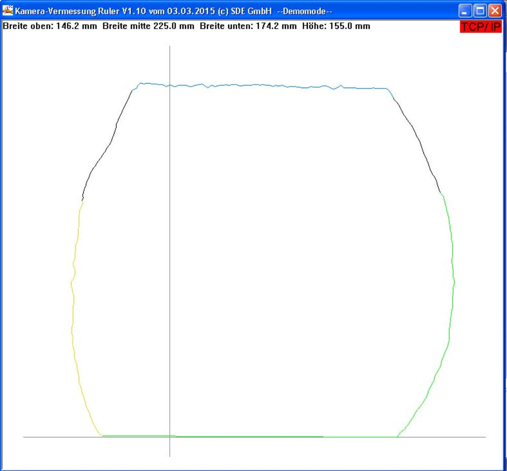
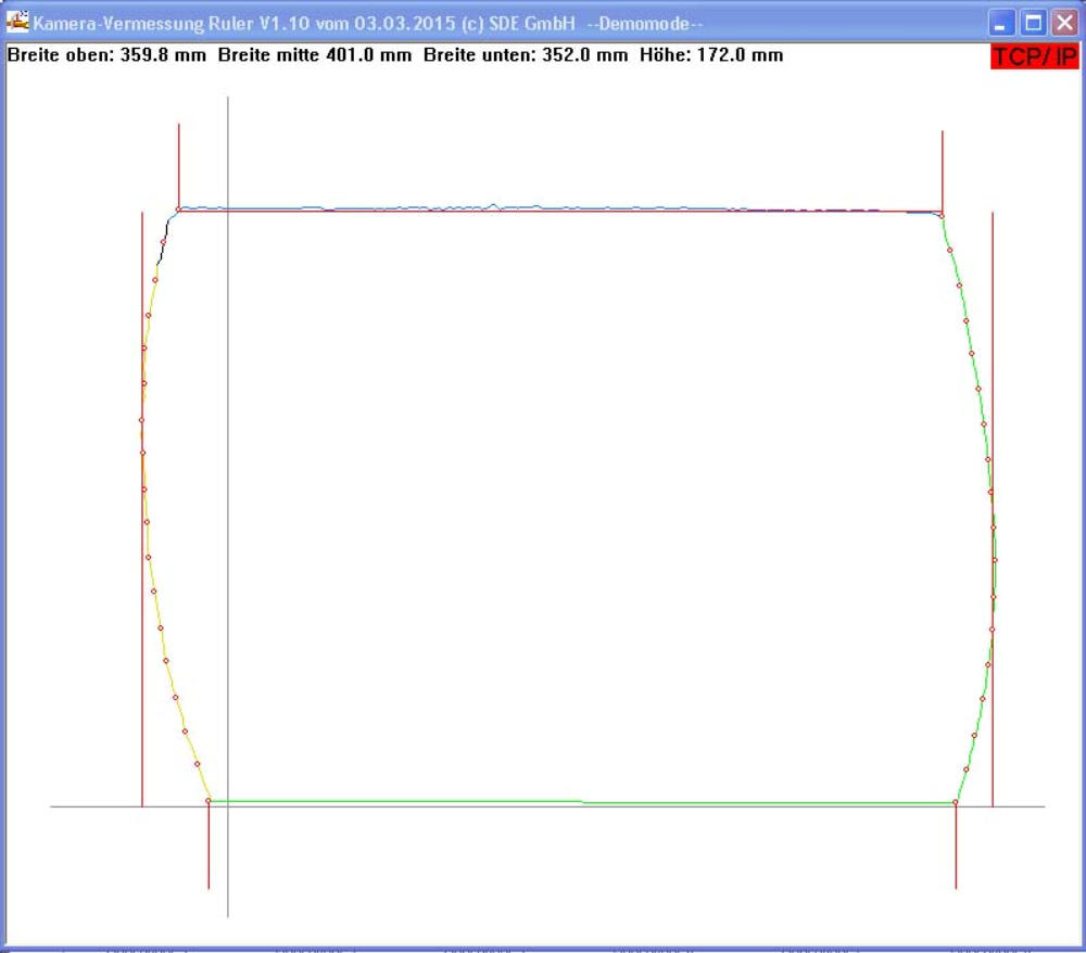
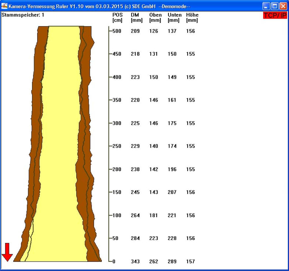
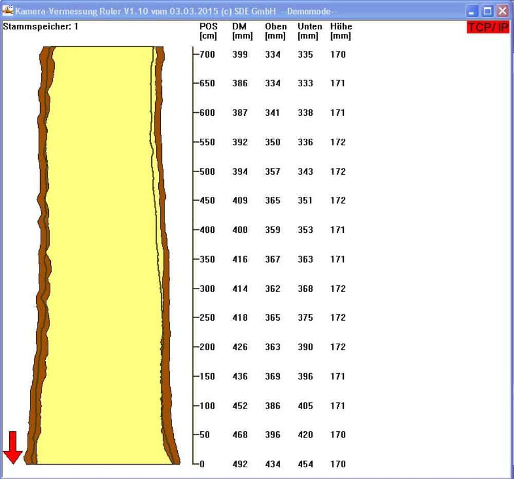
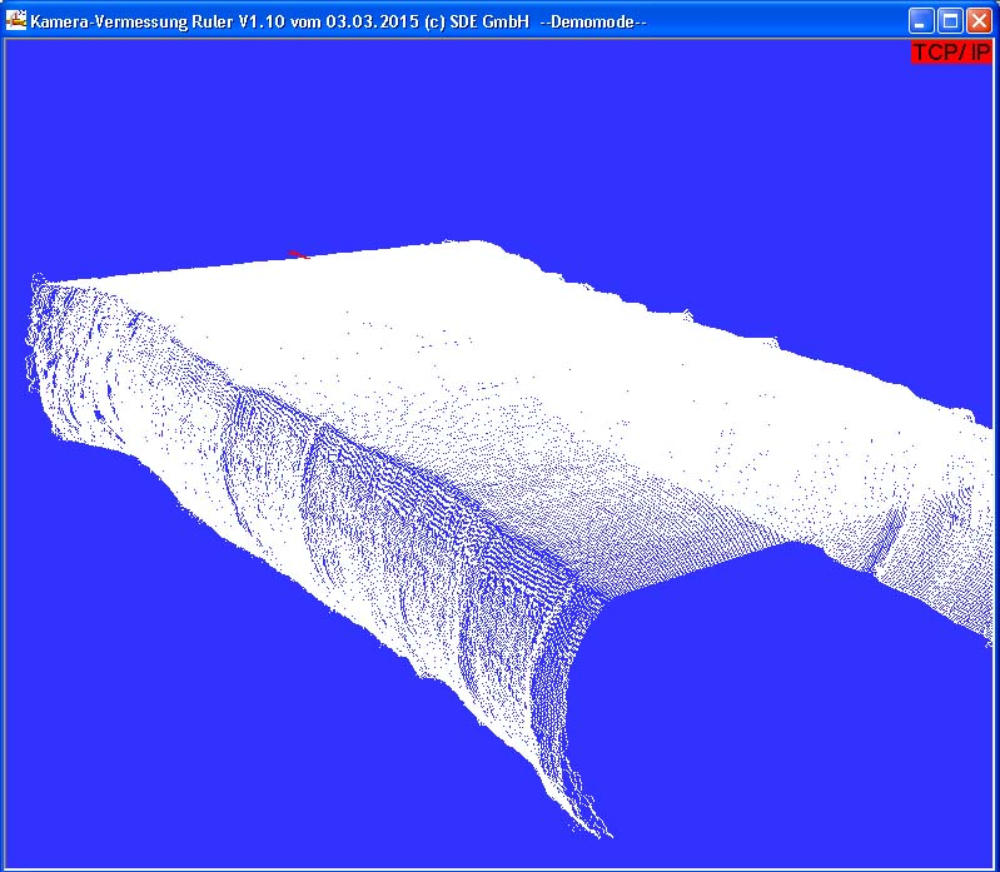
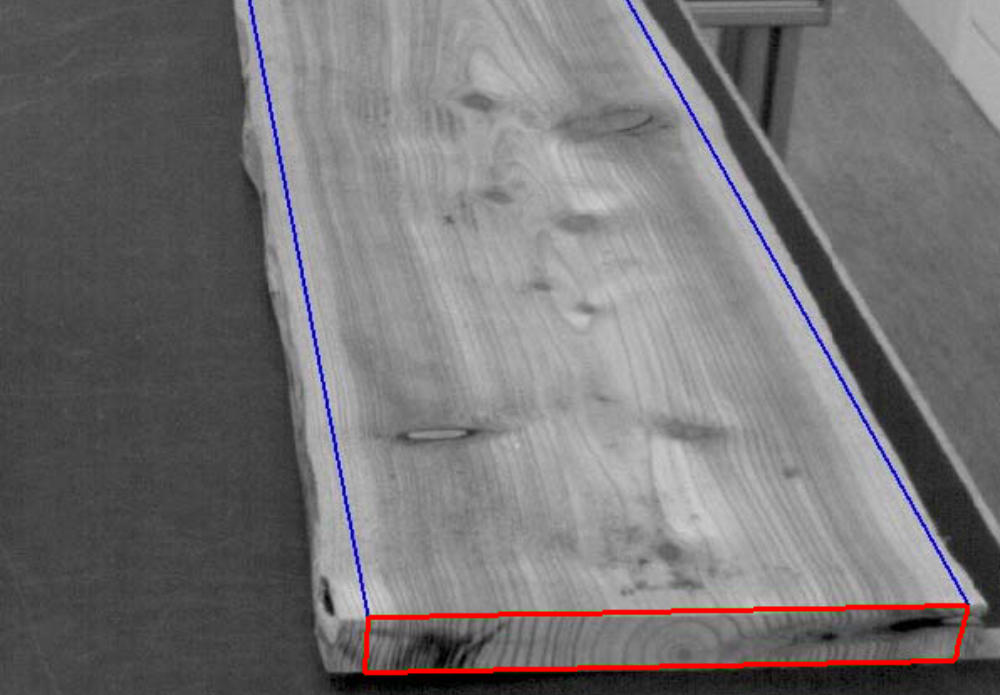
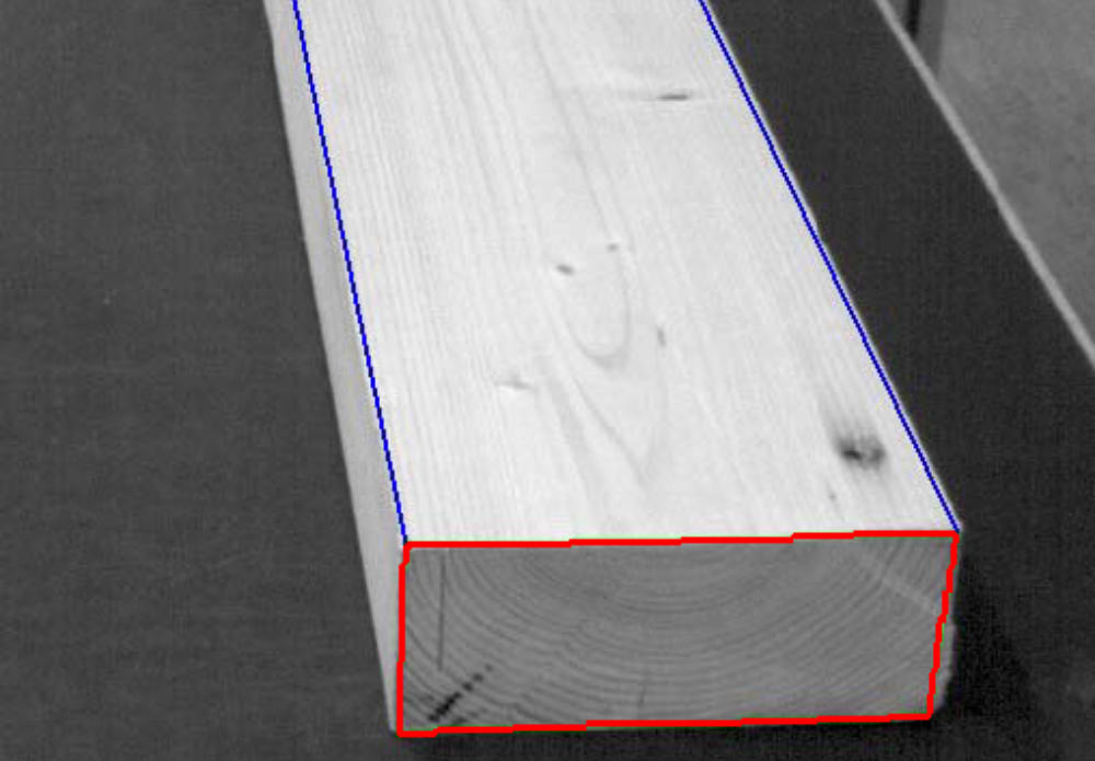
With the camera surveying the 3D contour of a log, a model, or a board will be
measured in continuous flow path .
For the capturing of the entire form there are usually multiple camera views required,
which are assembled calculational.
The analyzed data will be transfered to an optimisation.
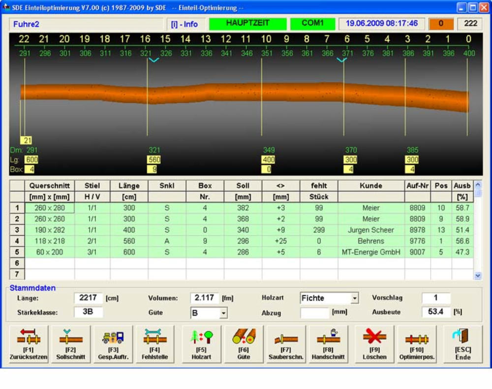
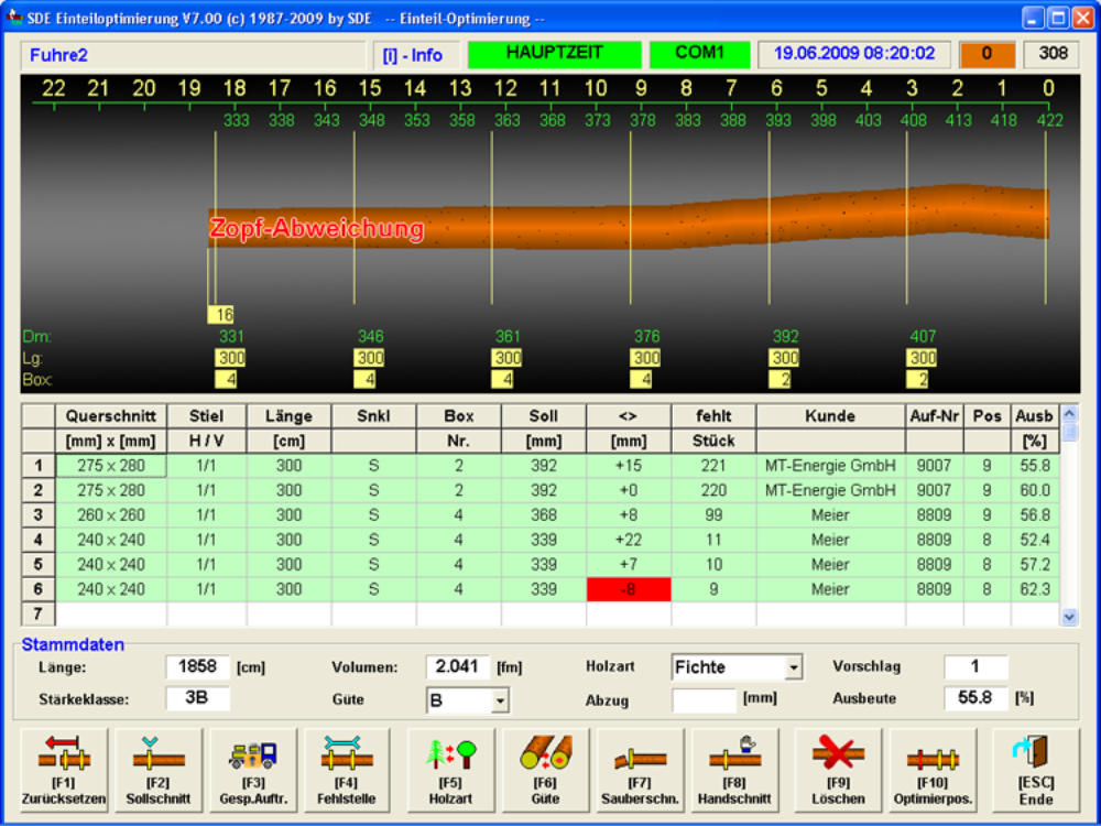
This program analyses the log data. The bend (if necessary) and taper is evaluated.
Now the operator has the opportunity to choose between several cutting proposals
that are calculated by the program.
Raw logs are transported on the conveyer to the correct position under the
drop saw and afterwards cut automatically.
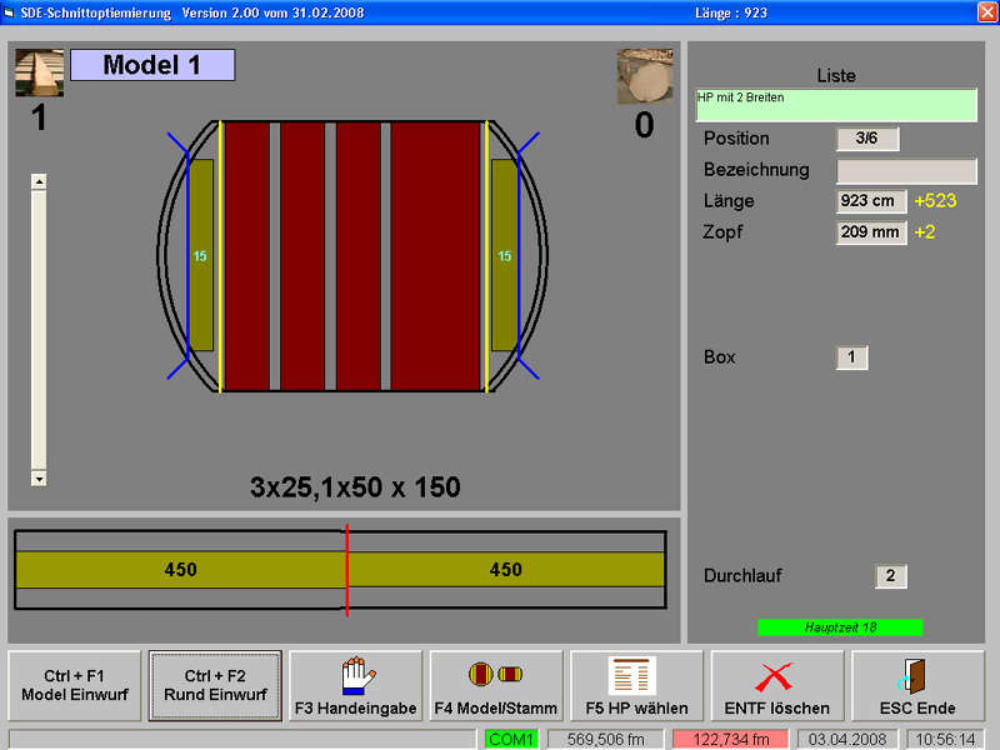
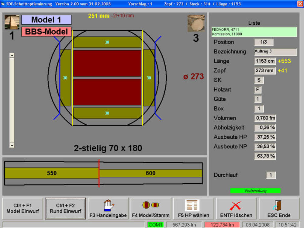
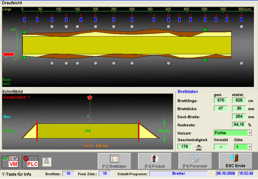
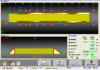
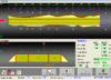
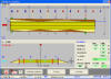
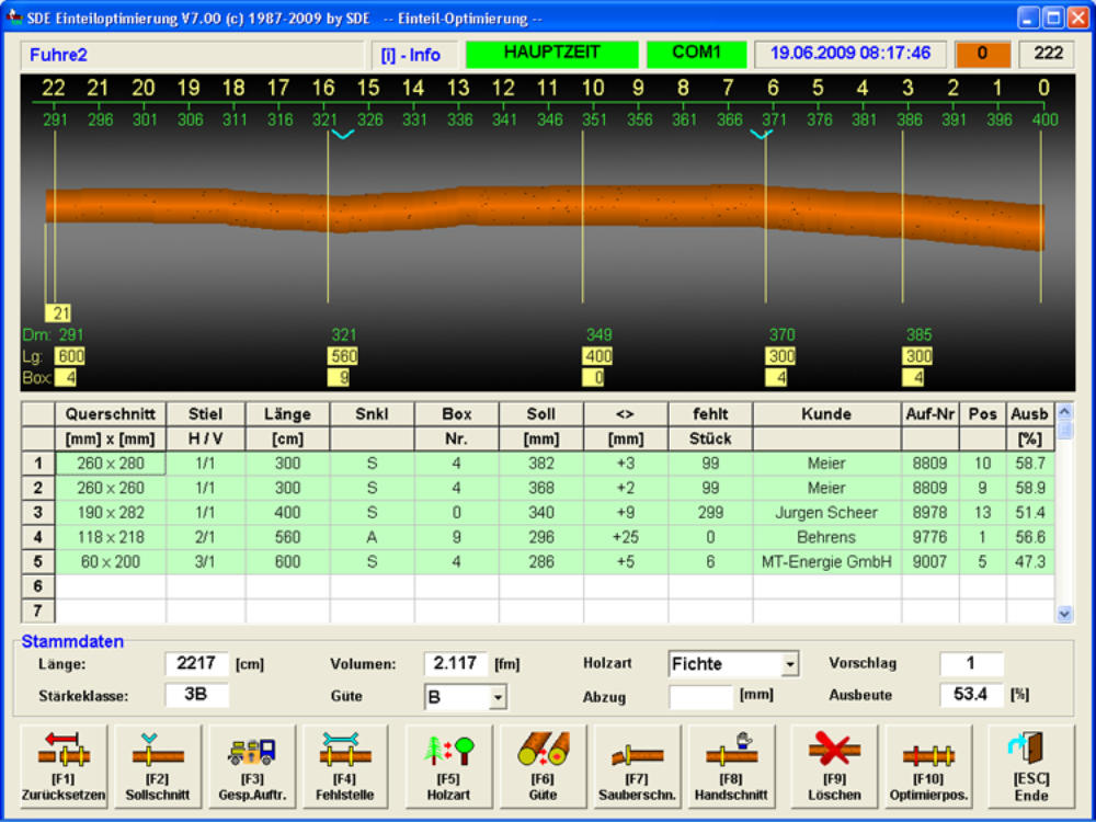
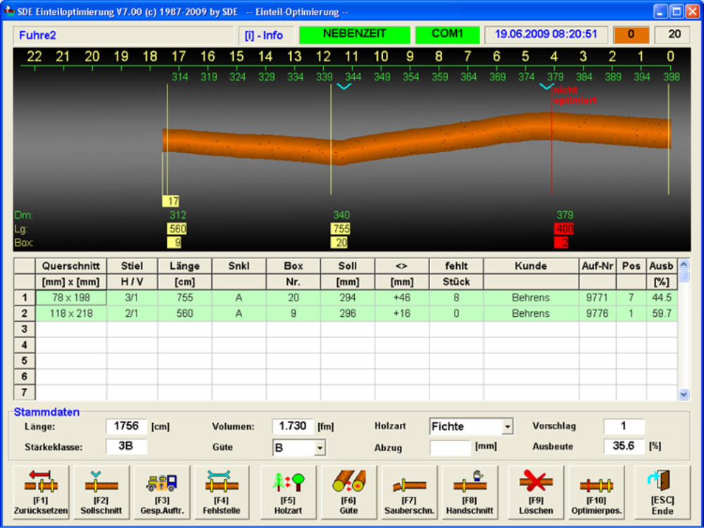
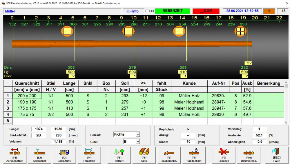
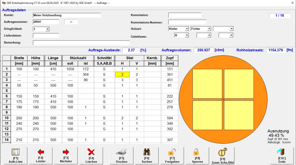
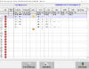
The upper image shows you the calculation module of the length optimisation,
the image below the corresponding visualisation module.
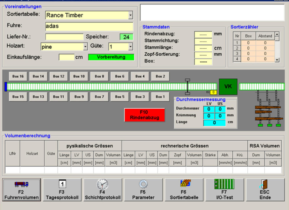
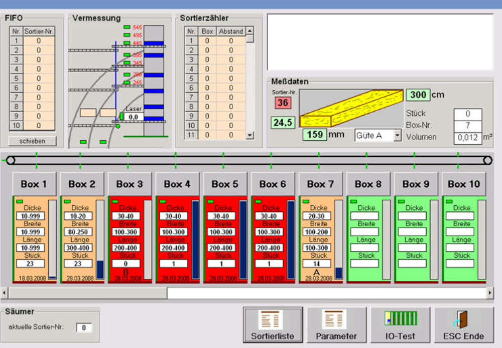
In the first step the log sorting system detects the volume of every log by using
a 2D respectively 3D measuring system. Than the transport and throw in into the
boxes that were defined before is coordinated.
In correspondence with the SDE Length optimisation a fully automised process
of the entire log sorting device is possible.
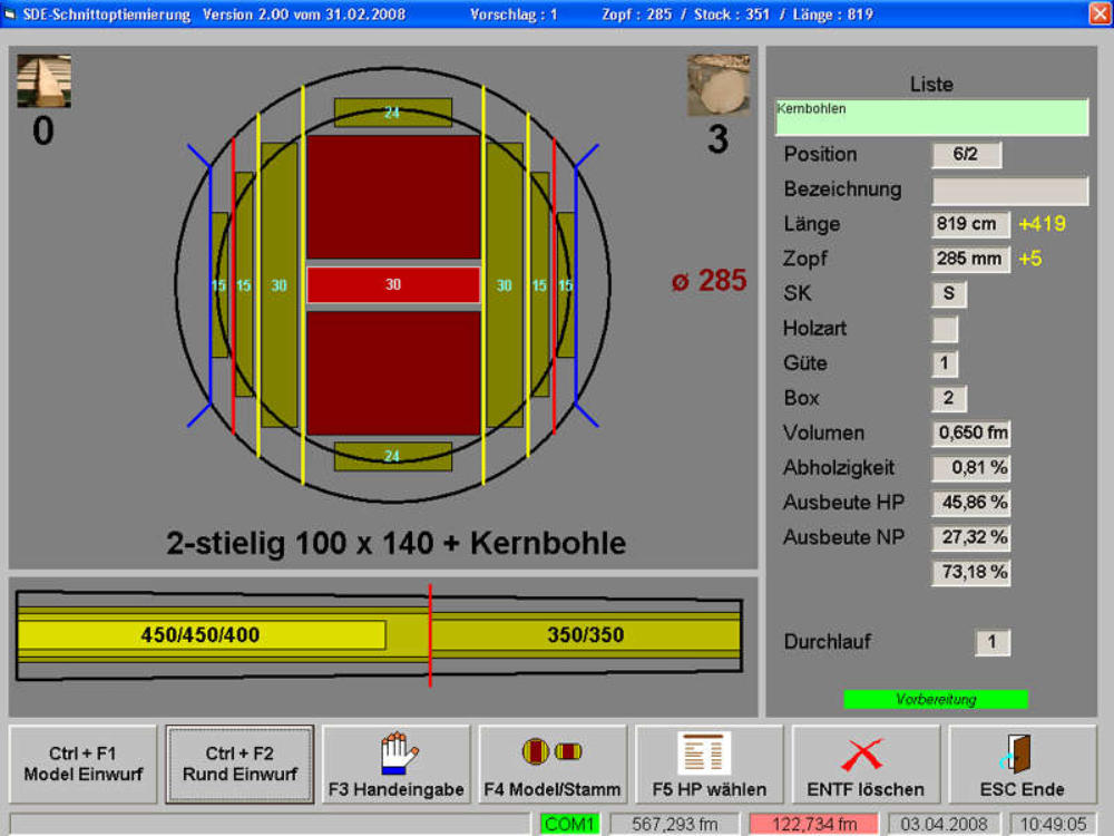
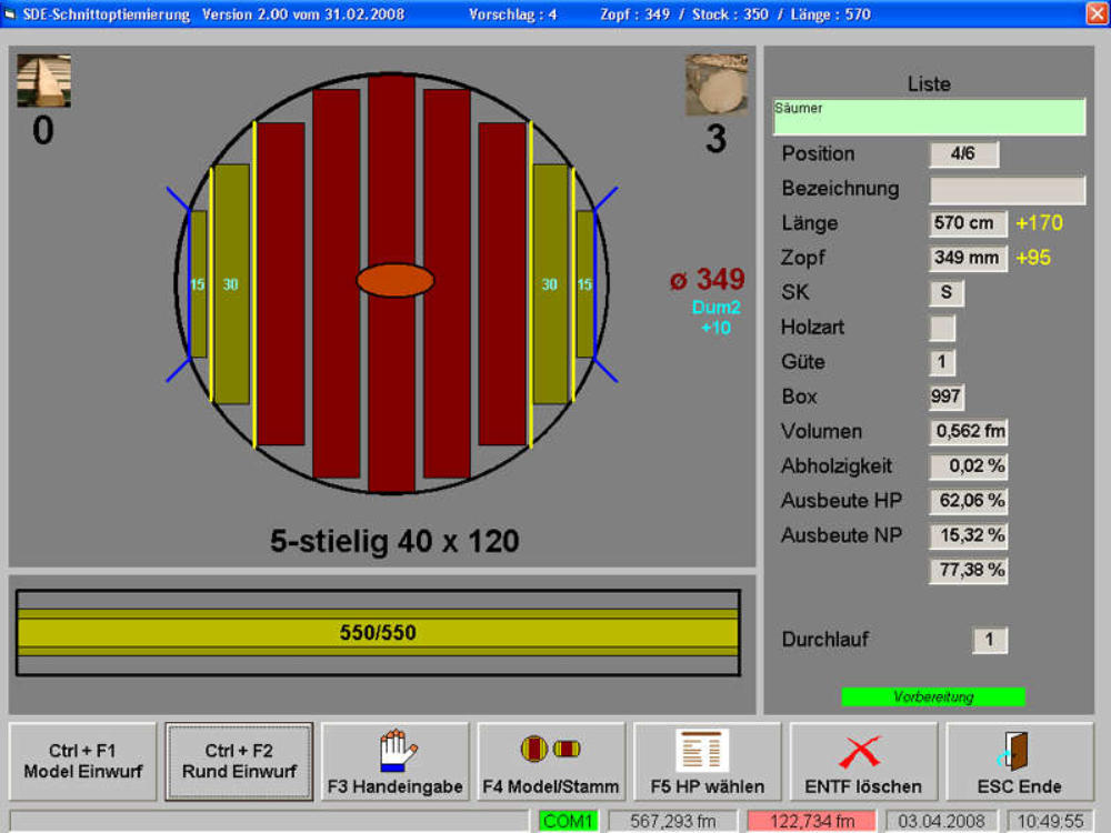
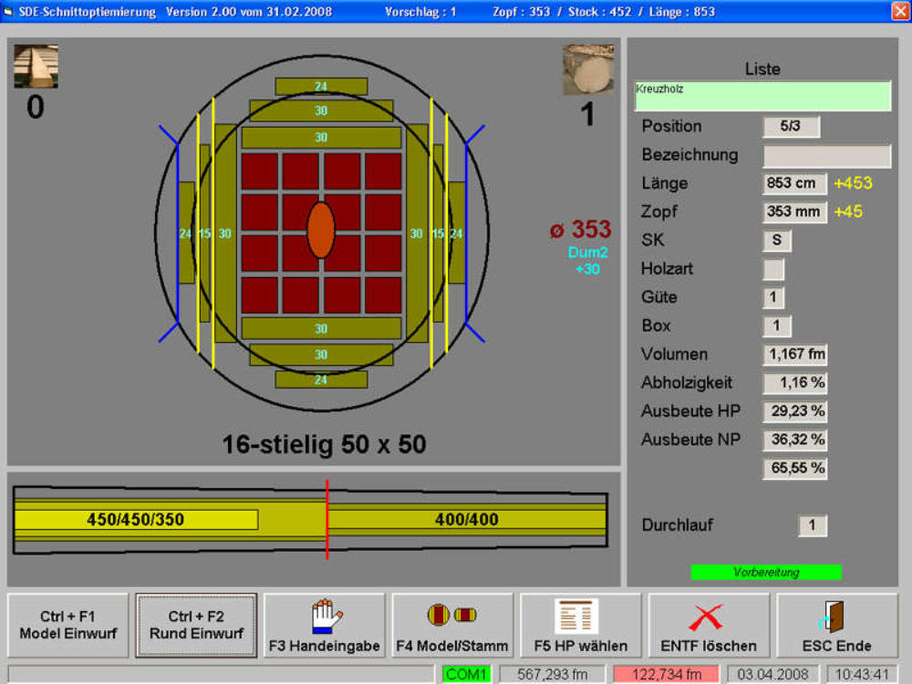
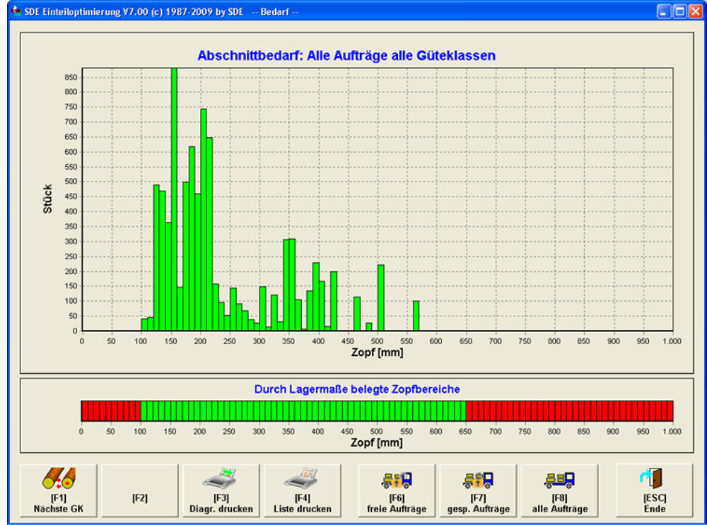
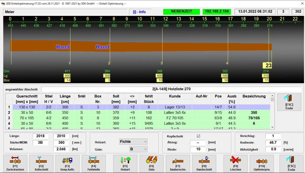
The SDE Sawing pattern optimisation is aligned to modern, quickly adjustable
Saw blades and Chipper canters.
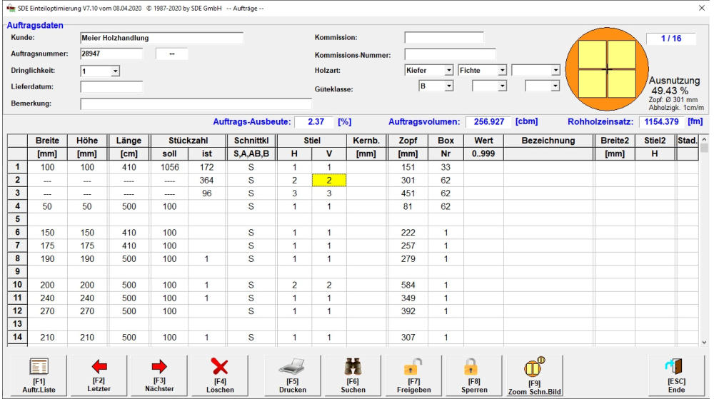
Based of the volume of every single log and under consideration of the purchase
orders the program generates a sawing pattern.
The system calculates side products under consideration of running costs.
The side products a optimised according to profit maximum rather that to yield.
Also the calculation of the chipper canter jump and board capping are
considered in the optimisation process.
Here you can find further examples of sawing pattern:
Order list
Sharp cut
Core plank
Quarter timber


Nonstandard
pattern
Two boards
SLS Model
BBS Model
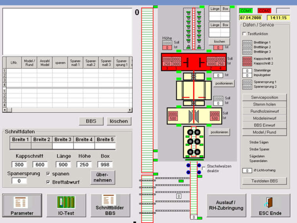
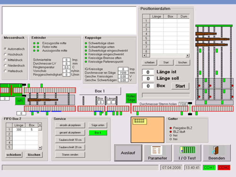
Basically this software module arranges the process and control of the entire saw line.
The operator can follow the process steps on the screen.
Both options are possible: One saw station in the line as well as two or
more saw station in the line.
These are the process steps controlled by this module:
Positioning of Chipper canter axe and saw axes
Log tracing within the entire line
Reporting of all sensors
Control of drives and hydraulic components
(e. g. prick roller, pressure roller, chain bed conveyor a. s. o.)
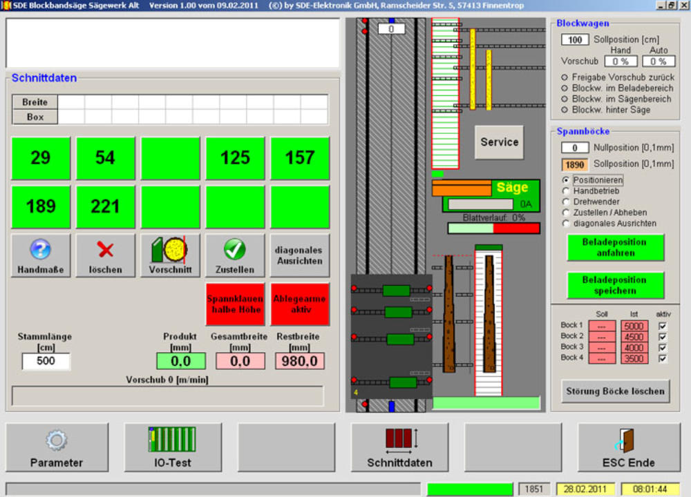
Our software for controlling a bandsaw works under
Consideration of:
up to 6 individually movable clamping blocks
implementation of a Chipper canter
including a chop saw is possible
short cycletimes
diagonal alignment of the log
high flexibility regarding product range
automatic infeed under consideration of
blade fluctuation
input current of band saw
fully automated process
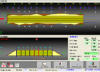
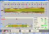
The SDE Säumersteuerung can control up to 6 variable sawing axes.
The Laser measures the board in cross direction.
There are up to 48 laser over and 48 laser below the Board.
For better length detection, light sensors can be attached.
The status of the laser or light sensors are shown in the visualization.
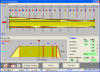
1. One board
2. 3-boards
3. 4-boards
4. Fixed saws
5. Shorted slats a
6. Shorted slats
b
7. Cut program
Profil-Scanner
Single-Profil
interpolation
point
Topview 1
Topview 2
measuring
points
Volume model

Camera surveying
Length optimisation
Log sorting
Sawing pattern optimisation
Automatic sawline


Log bandsaw


Edger control software
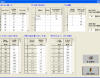
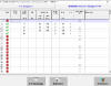
Here are some pictures of the user interface:
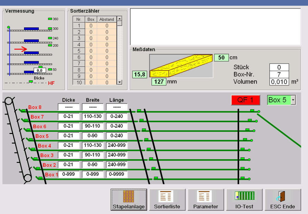
Board sorting

Level sorting
The principle of the level sorting is equal to those of the box sorting.
In this case to boxes for the boards are arranged horizontally.
That means that you have fewer boxes but more storage per box.
The sawing pattern optimisation program can be adjusted to defined sorting and
random sorting. One can distinguish between box sorting and level sorting.
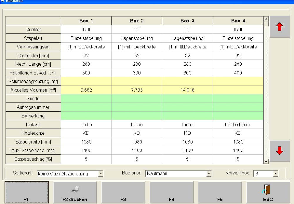
Box sorting
Initially the shape of every board is detected.
In terms of a random sorting the software takes over the decision for a box
independently based on the current sorting list.
Thus the sorting process becomes very flexible and it works always according
to the most urgent purchase order.
In accordance with the requirements of the saw mill operator the board sorting
system can be implemented as a defined sorting.
In this case the box numbers will be defined manually.
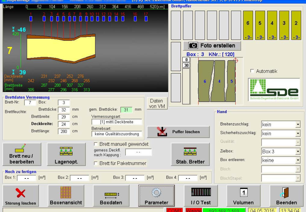
This software calculates the pick and place position of a portalrobot.
The board is stacked with vacuum sauger.
The contour of the boards is detected by laser measurement. The software will
calculate the optimum position and rotation of the boards for each layer.
The great advantage of this stacking method is the packing density.
The boards are then stacked into each other, so that only a few
stabilising planks must be placed.
The data will be corrected when a board is cutted by the length..
From the measured data, the sales widths and Lengths are determined.
These can be detained in a file for further processing.
The software supports automatically to sign the boards,
the processing of wood moisture and the package weight.
For quality assurance, each board can automatically photographed and
be traced by means of image file to each stack.
The product DrawCut shows the dimensions in a live image of a Camera.
So it is possible for example to find positions for a log bandsaw.
The on-screen dimensions are corresponding with the real coordinates
of the machine.
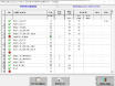
We have some proven software modules, which are usually adapted to the corresponding plant.

9. Fixed cuts
8. Board program
11. Profile for
machine setup

Visualisation
Mainmenue
Sample 1
Sample 2
Sample 3
Order
Distribution
Optimisation
Cut pattern
10. Administration
Manuel
editing
12. Block diagram
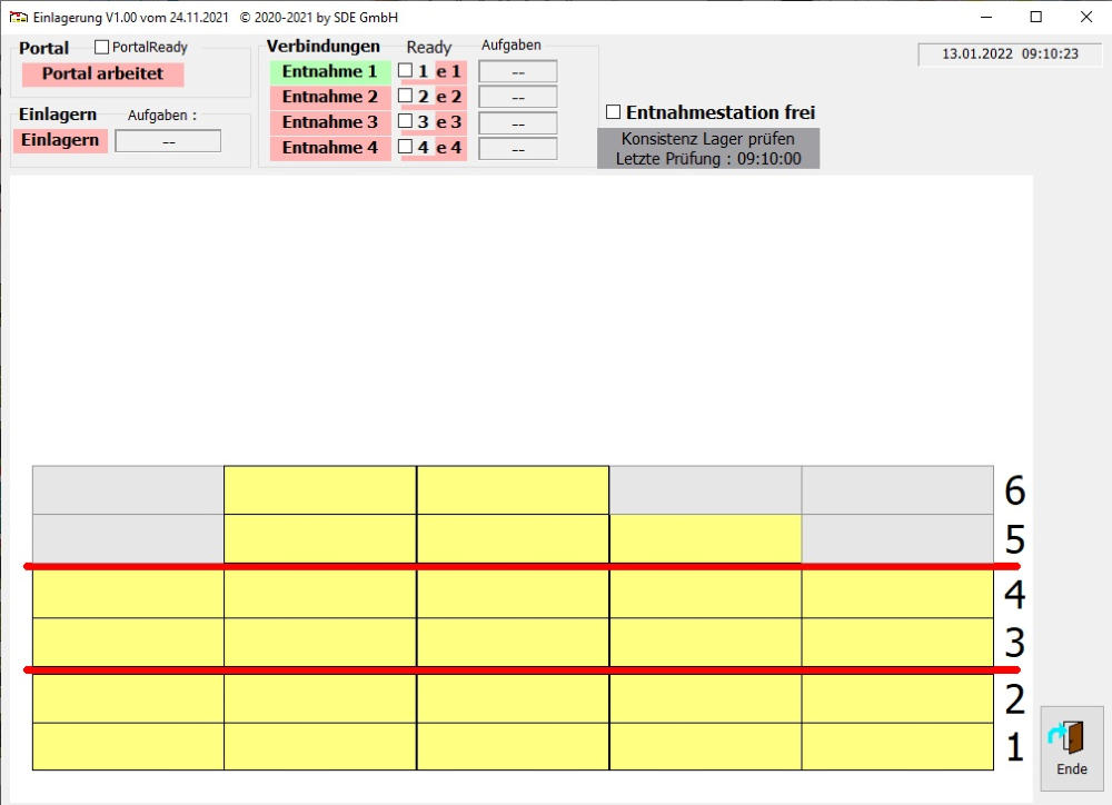
Stacking area storage

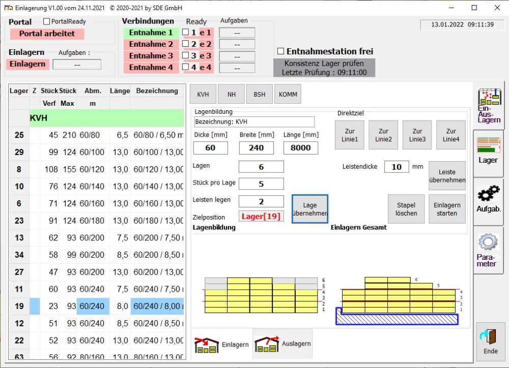

The program consists of 2 components
1. Storage and management
2. Outsourcing (is installed in the existing project at 4-stations).
The input stacks the specified lumber from a task package
into the storage bins created for it.
The software transfers to the portal robot the pickup positions, travel distances
and set-down positions for the lumber and any intermediate bars for stabilization.
(On the left a picture of the stock overview)
During storage, the lumber is placed in the appropriate storage bin.
The quantities, maximum stack heights, etc. are managed here.
Several wood designations (KVH,BSH...) can be stored.
so that the lists remain clear and are quickly accessible.
(On the left a picture of the input storage)
When stacking, different timbers can be taken from a pallet.
If woods have already been taken, you can deactivate them.
(On the Left a picture of the stack)
When removing from storage, first select the corresponding list of dimension (the
dimensions are sorted in ascending order).
After that, you specify the required number of pieces and confirm the input.
The lumber is then picked up fully automatically from the corresponding stack and
where placed at a predefined position.
At the moment there are 4 outsourcing places available.
(On the left a picture of the output stack)
In this type of storage, the timber (bars, beams, squared lumber and boards) are
simply stacked on the floor of the hall with a portal roboter.
There is no other device for aligning the wood. Therefore, the storage of different dimensions is relatively simple.